Texas Star DX 667V CW Transmitter To AMP Conversion
- Unsolder the wire from the key jack on the rear panel near the fuse holders.
- Locate the two standing capacitors (15pf and 33pf) near the relay and RF choke. Unsolder and remove the wire from the tops of the capacitors. Separate and remove the 33pf capacitor leaving the 15pf in place. Resolder the standing end of the 15pf capacitor to the adjacent pad on the board. This pad also connects to a wire from the rear panel S0239 connector (Radio). 3. Remove the 33 ohm resistor (ora-ora-blk) (and wire if present) located directly behind the relay. This resistor connects a RF choke to the oscillator board.
NOTE: Some units may only have a wire without a 33 ohm resistor soldered to this point. In that case remove the wire. - Unsolder and remove the large yellow capacitor (marked 2200K) connecting the center of the blue pot to the oscillator board. Do not remove the resistor connected to the pot.
- Locate the white block resistor and RF choke behind the meter. Unsolder and remove the 10 ohm resistor (brown-blk-blk) from the top of the 30K resistor (ora-blk-ora) beside the RF choke.
- Locate the wire soldered to Pin 1 of the Power switch (red lens). Unsolder the grounded end of this wire, and solder it to the 10 ohm 2 watt resistor (brn-blk-blk) located directly under Pin 1 of the Power switch (red lens).
- Unsolder and remove the oscillator board if desired.
Texas Star DX 667 Videos

Texas Star DX 667V CW Transmitter – Amplify Your Ham Radio Adventures
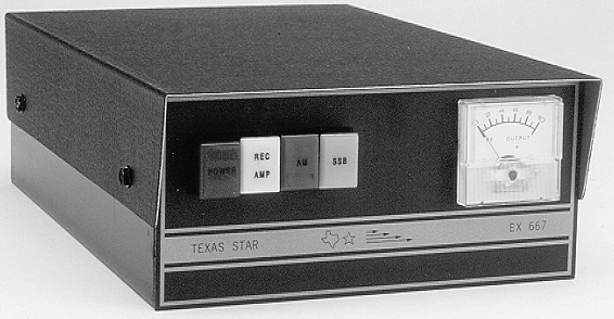
For ham radio enthusiasts, the Texas Star DX 667V CW Transmitter is a game-changer that brings power, reliability, and versatility to your 10-meter communications. Perfect for mobile or base station setups, this compact CW transmitter is designed to deliver exceptional performance for both seasoned operators and newcomers to the world of amateur radio. Get ready to connect across the airwaves with clarity and confidence!
What Makes the Texas Star DX 667V Stand Out?
- Superior Signal Strength
Operating on the 10-meter band (28.0 MHz to 29.7 MHz), the DX 667V provides a maximum power output of less than 5 watts RMS, meeting FCC standards for CW operation. With a frequency stability of 50 parts per million across a 0-50°C range, it ensures clean, reliable signals when paired with a tuned antenna. - Rugged and Portable Design
At just 6 pounds and measuring 3-1/4″(H) x 6-5/8″(W) x 10-3/4″(D), the DX 667V is built tough for mobile or home use. Its durable construction handles the demands of frequent operation, making it a trusted companion for any radio adventure. - Operator-Friendly Features
The DX 667V is packed with practical features for seamless operation:
- RF Output Control: Fine-tune your signal strength with ease, even with the green button engaged.
- Illuminated Meter: Track relative RF output during transmission with a clear, built-in display.
- Key Jack: A rear-mounted 1/8″ miniature phone plug connects effortlessly to your telegraph key for smooth CW operation.
- Dual SO239 Connectors: 50-ohm antenna and radio connectors simplify integration for break-in setups.
- Flexible Power Compatibility
The DX 667V runs on a 12-volt vehicle battery or regulated power supply, drawing less than 6 amps for efficient performance. It’s ready to go wherever your radio journey takes you. - Proven Performance
With decades of acclaim from the ham radio community, the DX 667V is a favorite for its reliability. One operator raved, “After 20 years, my 667V still outperforms newer models.” Whether you’re working DX or chatting locally, this transmitter delivers.
Ideal for CW Enthusiasts
Tailored for Continuous Wave (Morse code) operation, the DX 667V offers excellent frequency stability and harmonic suppression (>30dB down) for compliant, high-quality signals. A valid amateur radio license is required, and operators must follow local regulations.
Customize with Confidence
Advanced users can modify the DX 667V into an RF amplifier, as outlined in online resources. This adaptability appeals to technicians eager to personalize their setup. Always consult a professional to ensure compliance with FCC guidelines.
Start Transmitting Today!
Ready to enhance your ham radio experience? The Texas Star DX 667V CW Transmitter is available at trusted retailers like Copper Electronics and eBay. Don’t wait to own this legendary piece of equipment—order now and take your 10-meter communications to new heights!
Sources: Web ID 15, Web ID 7, Web ID 11, Web ID 12, Web ID 17